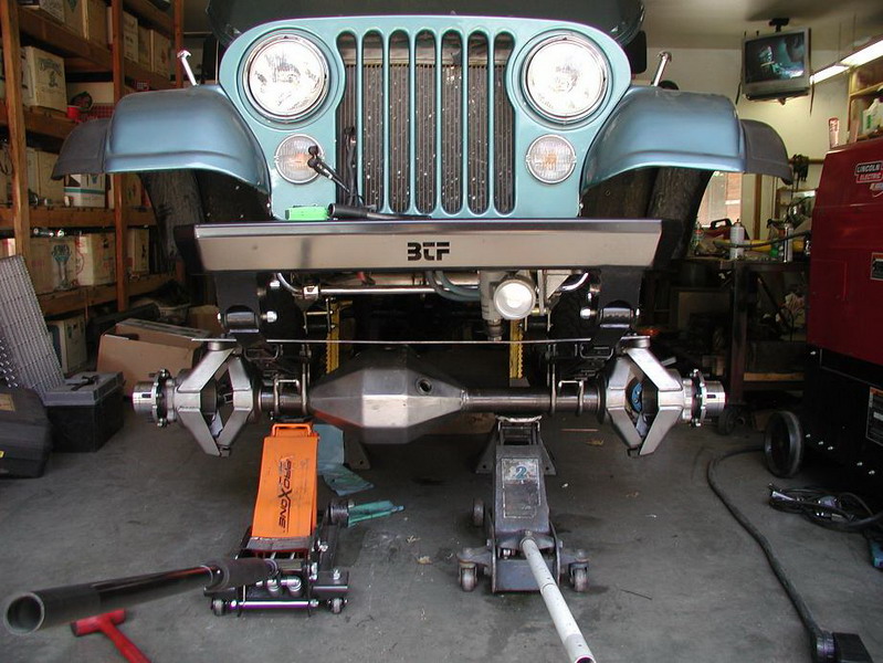
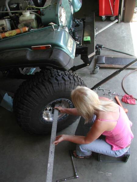
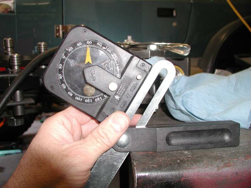
June 20, 2007 -- The first thing I did to actually get started with this build was to set up the front end for cutting the tubes. This is how it works...the front housing with the third member bolted in place is put in the Jeep with the spring pads (ordered from MORE) in place and the u-bolts tight enough to hold the front end where it is placed, but loose enough to move it around a little. The pinion is centered properly to line up with the output of the transfer case. Then, to be sure there was enough steering angle at the desired width, a tire was put on the short side where the knuckle could articulate (on the long side there was too much axle tube). The tires were turned and the angle checked using an angle square gismo like shown in the picture. Yeah, that's my wife helping. She has her own Jeep, so she isn't allergic to helping in the shop!
June 22, 2007 -- Next comes setting up the knuckles. This MUST be done with the jeep sitting with normal weight in it, level as if the tires are mounted and on the ground, and the full weight on the front end so the springs are under tension the same as if it were on the road. The third member is reloaded into the housing and it is put in place again with the spring pads and u-bolted into place. Then the pinion angle is set for the proper driveline angle and both pads are tacked in multiple places. After that the camber and caster need to be set perfectly before the knuckles are tacked on. I was having trouble getting them held in place for camber at the same time the caster is properly set, so I designed and built a jig to do it right.
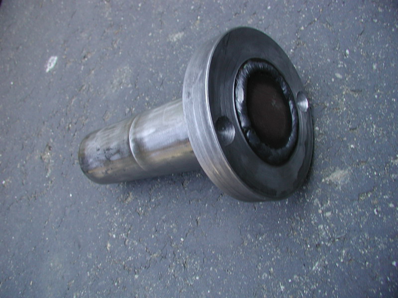
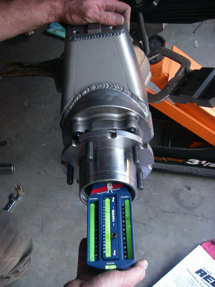
This is the jig. It slides into the tube with the assembled knuckle....
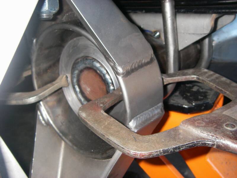
...and then it clamps up like this. This holds the camber at 0 degrees while allowing the the knuckle to be spun on the housing to set up the caster.
I used a Rebco caster/camber gauge available from Summit Racing. It is relatively inexpensive and works very well. I've used it for several front ends. I won't go through how it works here, but suffice it to say that it is set up for 0 degrees camber and 7 degrees positive camber on each side. Once it was set up, each knuckle was tacked in place.
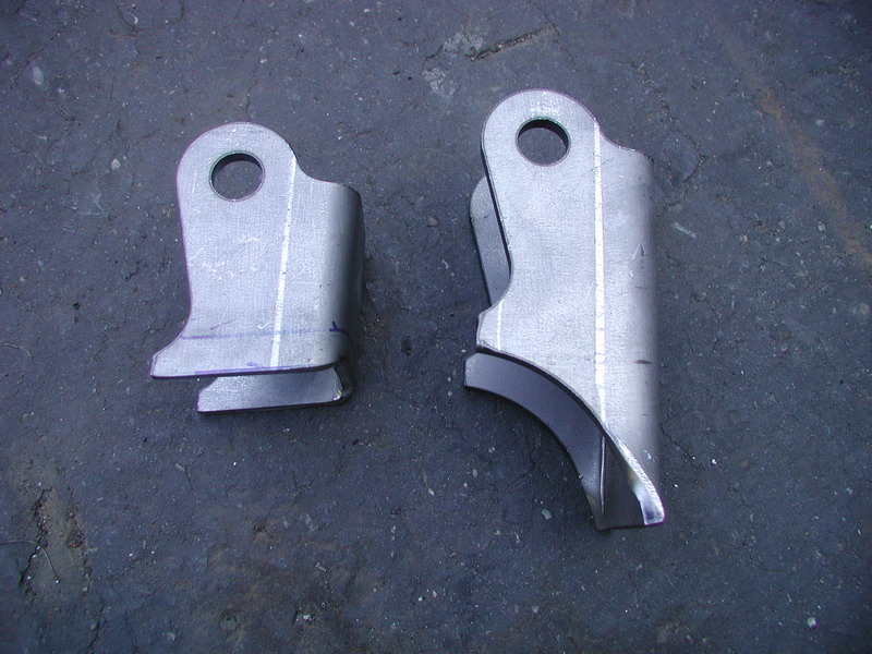
Before final welding, all the pieces have to be in place. This is a shot of a MORE generic shock mount (on the right) modified (on the left) to mount to the inner C instead of the axle tube. One was modified for each side and tacked in place. I also put the steering arms and tie rod on temporarily and built a ram mount for the hydro-assist. It was tacked to the top of the axle housing.
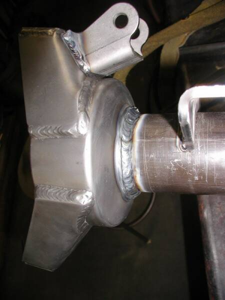
A shot of the knuckle welded in place with the shock mount on the top of the inner C.
As you can see, the knuckle allows for almost 60 degrees of turning at width I have it set. Obviously, I won't set it up for that much (impossible because the u-joint in the axle will bind), but I know I have plenty of room to work with, and that's what matters. Once this is done, it's time for some math. In order to get the tubes cut to the proper width, the distance between the outside of the springs is added to the distance taken up by the knuckle, hub and brake width multiplied by 2 (two sides, right?). That amount is subtracted from the desired width and then divided by 2. This will get the amount of tube distance from the outside edge of the spring pad to the desired end of the tube, or where it needs to be cut. This is measured and marked on the tube very carefully with a Sharpie. Then the front housing is pulled out, the third member removed, and the tubes cut with a portable band saw. Of course I measured it at least 4 times and checked the math in multiple directions. After that, I had a buddy come by and check the figures again, just to be sure.